ServoSensor™ Software
ASCII S-Series ServoSensor™
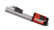
Produced through an industry synergy, an ASCII ServoSensor™ offers an easy communications format for interfacing to host controllers, such as PLC's and PCs. The unit maintains the features of the older 777 model with some features enhanced. The ServoSensor™ motion controller was co-developed by Paw-Taw-John Services, Inc. and Temposonics® Sensors Division. Manufactured by Paw-Taw-John Services, Inc. in Idaho, the platform for the unique design is an Temposonics® R-series magnetostrictive linear position sensor.

ServoSensor® Description
The S-Series ServoSensor® is a complete servo controller installed and interfaced inside an Temposonics® R-series platform. It consists of a Servo Controller Module (SCM), driver module (DM) and sensing element (SE) combined inside the sensor head body. Temposonics® proprietary technology is integrated directly into the SCM. This integration in the SCM provides the Servo Sensor™ Controller with very fast displacement measurements and servo control outputs. Hydraulic cylinders can typically be positioned to .001".
ServoSensor Software Setup Download.zip
Use this version for all ASCII ServoSensors™.
ServoSensor™ Specifications
Features
- Two new velocity loop window selections
- 1"/sec to 400"/sec..01"/sec to 40"/sec
- Discrete output can be programmed
- Operates from single +24 Vdc power supply
- Low supply current- typical 100mA with current controlled devices
- Voltage or current drive output
- Single cable run to ServoSensor™ Controller
- Servo device interfaced at ServoSensor™ end cap
- 1 millisecond Servo Loop update time
- Two wire RS-485 network compatible
- Up to 26 units per link
- User selectable Baud Rates
- 16-bit CRC error checking
- Visible indications for power and status located on end cap
- Same robust design as Temposonics® R-series sensor
- Four user selectable modes of operation
- Reverse polarity protected
- SD protected
ServoSensor™ Setup Software
- PTJ Servo Control Center software provided
- Operates under Windows 95/98 up to Windows 10
- Programmable port location used to program the ServoSensor™ when the host controller can not
ServoSensor™ Applications
- Hydraulic cylinders - linear motion
- Pneumatic cylinders
- Linear measure in control of ball screw applications, etc.
- Hydraulic or Profile Style Rod
Certifications
- CE Certified
- EN50082-2 Immunity
- N50081-2 Emissions
- FCC Part 15 Subpart B
- Industry Canada ICES-003
- Tested to IP67 Standard
Industry Applications
- Aerospace
- Automotive
- Food products industry
- Metal manufacturing
- Plastic manufacturing
- Steel manufacturing / production
- Wood products industry
Component Descriptions
Pressure Housing
- Rod style, hollow stainless steel tube for basic mounting structure
- Inserts into hydraulic / pneumatic cylinders with bored pistons
Sensing Element
- Self-contained magneto-strictive device anchored inside the main body of sensor cartridge
Driver Module
- Provides power conversions for driving the SE
- Supplies power for SCM
- Provides data control interfacing to SCM
Servo Control Module
- Consists of Temposonics® proprietary data acquisition technology, high speed micro controller, serial interface, servo driver and a power conversion device.
End Cap
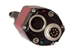
- Houses one 8-pin female connector for servo cable, one 8-pin male connector for com cable
- Red and green visual status indicators (LED's)
Hardware Specifications
Drive Output
- Output: current, thermal and short circuit protected
- Range: 0 to +/- 10 Vdc or 0 to +/-50 mA, factory set
- Resolution: 12-bit
Loop Update Time
- 1 mSec to 110"
Velocity
- 0.1 to 400"/sec @ 0.001" resolution
Resolution
- In Inches 0.0005" to 32.0" 0.001" to 65.0" 0.002" to 131.0"
- In Millimeters 0.01 mm to 655.35 mm 0.02 mm to 1310.07 mm 0.04 mm to 2621.40 mm
- Inches or millimeter resolution set at factory per time of order
Discrete I/O
Isolation
- 2500 VAC - Three source 24 Vdc inputs - One source 24 Vdc output; 25 mA max - 3 microsecond on/5 microsecond off - Maximum input voltage: 28.8 Vdc
Power Requirements
- Voltage: +24 Vdc, -5 to +5%
- Current: 100 mA typical with +/-50 mA drive output
- DC-DC converter isolation: 1000 Vrms
Temperature
- Voltage: Range -40 to 75 degrees C
Dimensions
- ServoSensor™ length: Stroke dependent
- End cap length: 6.5 inches including straight connectors
Communication Interface
- RS-485 two wire
- ASCII code with 8-bit
- 16-bit CRC
- Baud rates: 19.2, 38.4, 57.6, 115.2 kb
- See ServoSensor™ manual for communication instruction set
Visual Indicators
- Indicators located at end cap of controller
- Red lamp indicates power applied
- Green lamp indicates controller status
- Green lamp flashes at rates that equate to operation or faults

System Integration
Single Unit Client System During normal operations, the ServoSensor™ communicates serially with the host computer in time frames based on the baud rate. The host computer monitors status and position information sent by the unit.
When a new target is necessary, a target and velocity command is sent one time. If target is acknowledged we return to reading position and status.
An operator interface would be connected to some form of input/output device installed locally in the computer or externally.
Multi-Unit Client System A multiple Client system is integrated similar to a single Client system, except ServoSensors™ are installed on an RS-485 two-wire network. A host computer requires an RS-485 interface. An RS-485 card can be used. New PLC modules loaded with translator software also can be used for multiple axes. Address loading of the ServoSensor™ on a network would be required and would be accomplished using program software.
Discrete Control Inputs The ServoSensor™ Controller has three independent discrete +24 Vdc inputs for control of the servo loop. One input is called the set enable, one is called controlled device power and the third is called trigger.
Discrete Control Output The discrete output is a 24 Vdc signal that is programmed to act differently in two modes. With the first mode, the output will come on when a set is achieved and within a target window specified in the program. The second mode is used with the cycle program mode. When a cycle is complete the output will come on.
Probe Lengths
Probe lengths are available in one inch (1") to sixty-five inches (65.0"). For longer lengths consult the factory. Probes are available in inches or millimeters.
ServoSensor™ Application Interfaces
The ServoSensor™ Communicate over RS-485, With ASCII command to control and read sensor data. List of the platforms ServoSensor™ integrated to:
- Automation Direct F4-CP128 Coprocessor module for 450 PLC
- Automation Direct Do-more H2 PLC
with RS-485 Communication Module - Allen-Bradley Control Logix MVI (Multi-Vendor Interface) module
Pulse Mode Manual Download - Allen Bradley SLC500 MVI (Multi-Vendor Interface) module
MVI Manual1 Download
MVI Manual Download - RS-485 Communication Cards (Installed within a PC)
USB to RS485 Converter
Don't hesitate to contact us if your favorite platform is not on this list, we can help with that.

